1. Home
  2. products
  3. demountable wall systems
  4. Full Height Glass Partition Systems

Full-Height Glass Partition Systems

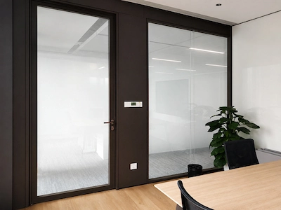
A full-height glass partition extends from the finished floor to a defined upper termination, such as a suspended ceiling, structural slab, soffit, or another project-defined upper condition. The type of upper termination affects how the partition is supported and connected to the building.

It remains a non-load-bearing interior partition, and the full-height label does not by itself establish acoustic, fire, or stability performance or automatic project approval.

Full-height means

A wall extending to the defined upper termination

A clearly defined ceiling or upper support condition

Support and connections suited to the actual site conditions

Full-height does not mean

A fixed or universal wall height

A separate wall system

Guaranteed performance or automatic project approval
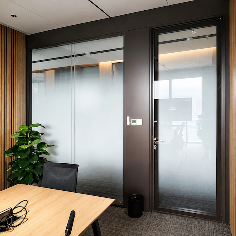
Finished Floor

Defined Upper Termination

Side Interface

Door Opening

full height glass partition extending from finished floor to defined upper termination with door opening and side interface

Which SG System Should You Start With?

SG-40, SG-86, and SG-100 provide different starting points depending on the intended appearance and proposed wall requirements.
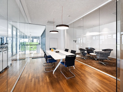
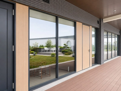
slim profile full height glass partition used as an initial sg 40 review direction
Slim, visually light profile

Consider SG-40 first when a slim, visually light appearance is the main design priority.

commercial full height glass partition route for sg 86 configuration review
Versatile option for commercial interiors

Consider SG-86 first for common commercial interiors and projects that may use different glass or infill configurations.

deeper full height glass partition route for sg 100 review in more complex wall layouts
For taller and more complex wall layouts

Consider SG-100 first for taller walls, more complex wall elevations, increased privacy requirements, or more demanding door-opening conditions.

To choose which system to review in detail, check the wall height, wall elevation, glass or infill configuration, door opening, and connections to the ceiling, floor, and adjacent building surfaces.

Use these systems as starting points for choosing a configuration; their names do not represent fixed performance levels.

Which Glass Configuration Best Fits the Project?

Start with the required visual privacy, preferred appearance, and intended wall construction. Each option uses a different glass position, wall build-up, and approach to visual privacy.
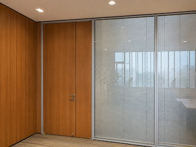
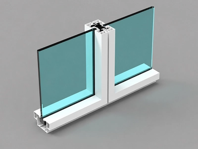
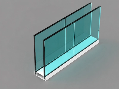
double glass partition with integrated blinds for adjustable visual privacy

Double Glass with Integrated Blinds

For adjustable visual privacy

Choose this option when occupants need to switch between clear visibility and visual privacy within a double-glass partition.

Glass options: SG-86 and SG-100 commonly use 5 or 6 mm glass per pane. For selected SG-100 projects, 6 or 8 mm glass per pane may be considered after project review.

center single glass module route shown in section detail

Center Single Glass

For a clean, centered single-glass appearance

Choose this option for a simple glass line positioned at the center of the wall frame.

Glass options: 10 or 12 mm tempered glass. For selected projects, 6 mm + 1.52 mm PVB + 6 mm laminated glass may be considered.

double sided glass module route for full height wall configuration review

Double-Sided Glass

For glass on both faces of the wall

Choose this option when the design requires separate glass panels on both sides of the wall.

Glass options: 10 or 12 mm glass on each side. Selected configurations may use 6 mm + 1.52 mm PVB + 6 mm laminated glass on both faces.

Blind and Privacy Options

Standard color: silver | 16, 25, or 50 mm slats | Manual rotary control | Electric tilt | Electric lift and tilt.

Confirm the wall elevation and building connections before finalizing the detailed configuration. These glass configurations do not, by themselves, establish acoustic or fire ratings or guarantee the performance of the complete wall assembly or installed system.

How Should the Wall Elevation Be Divided?

After choosing the glass configuration, define the module layout, pane divisions, final module, and visible joint details.

Key Dimensions

≈5 mm: visible frame-to-frame gap between adjacent SG-86 or SG-100 aluminum-framed modules in standard configurations.

25 mm: applies separately to the blind-module frame width, center-single-glass frame width, and center-single-glass U-channel height.

≈2 mm: clear joint for selected butt-jointed 10 or 12 mm glass panels.

≈1000 mm: typical module width for initial elevation planning; adjust the final module to fit the actual wall length.

≈980 mm: typical finished width of the blind assembly within a 1000 mm module.

≈1150 mm: recommended planning width for a wider blind assembly.

≈3 m²: typical pane-area guideline, subject to the selected glass configuration, access, transport, handling, and installation conditions.

4 mm: gap between adjacent SG-86 or SG-100 integrated-blind modules.

Wall Elevation Checklist

Use a full-height pane where pane size, access, handling, and installation conditions allow.

Add a horizontal division where required by the elevation design, transport, or site access.

Resize the final module to fit the actual wall length.

Review narrow corner and door-side modules separately.

What Does the Wall Connect to at the Top?

Identify the actual upper support condition before confirming the full-height wall configuration.

Structural Slab or Solid Ceiling

A direct connection may be possible

Confirm that the surface and fixing conditions are suitable for the selected wall system.

Gypsum Ceiling

Check the support above

The gypsum board alone is not the supporting structure.

T-Bar Ceiling

Connect to suitable support above the ceiling grid

The ceiling grid should not be used as the wall’s only structural support.

Open Ceiling

Use a suitable structural fixing point

Review the proposed connection to the slab, beam, or another suitable structural support.

Before Confirming the Top Connection

The visible ceiling finish may not be the actual structural support for the wall. An allowance of approximately 10 mm applies only to minor local surface unevenness—not to deflection, settlement, movement, sloping surfaces, or unsuitable substrates.

Above-ceiling acoustic treatments and fire barriers should be reviewed separately for the project.
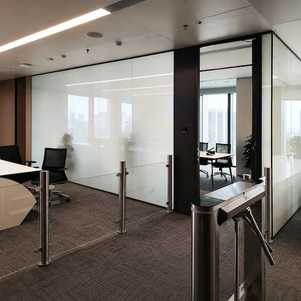
full height glass partition meeting the ceiling condition for head connection review

How Do the Floor and Side Conditions Affect the Wall Connection?

Confirm the finished floor level, supporting structure, and adjacent building surfaces before selecting the base and side connection details.
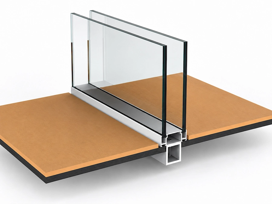
base connection detail for full height glass partition on finished floor

Base Conditions

Finished floor: An adjustment of approximately 15 mm may accommodate minor local level differences along a typical wall line.

Special floor areas: This adjustment does not apply to door openings, floor-spring locations, threshold-free transitions, expansion joints, or continuous or irregular slopes.

Raised floor: Identify a clear route to suitable support beneath or through the raised-floor system.

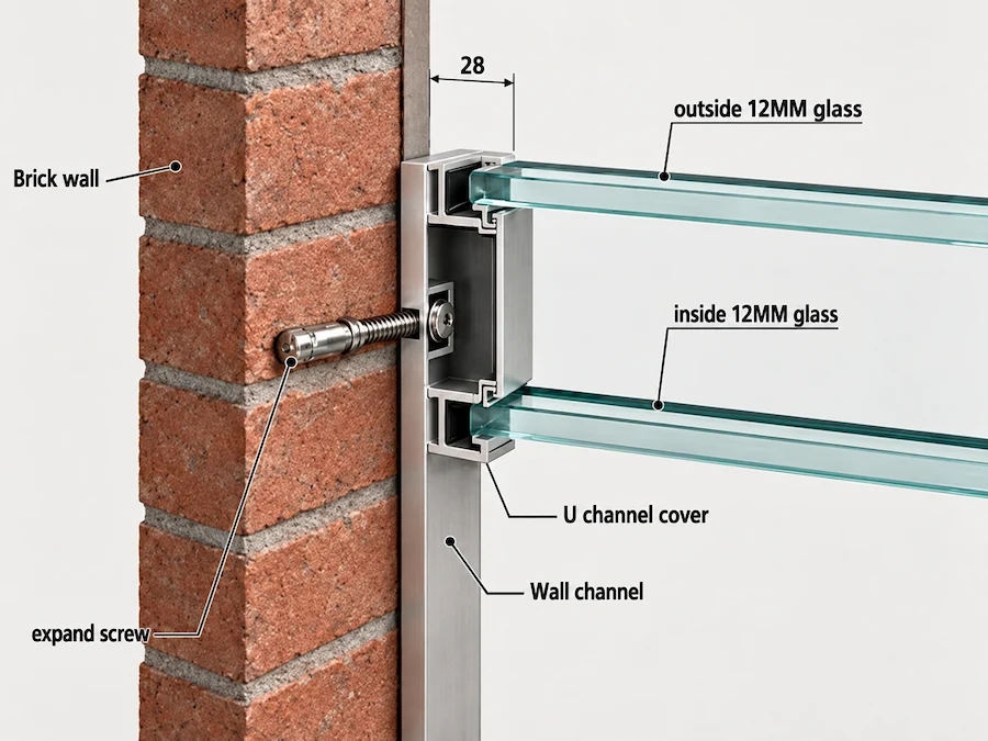
side wall connection detail showing glass partition interface with adjacent wall

Side Conditions

Solid wall or column: A direct lateral connection may be possible where the surface and fixing conditions are suitable.

Curtain wall or lightweight wall: Identify suitable structural support or a connection point rather than relying on the surface finish alone.

Door-side or side-wall adjustment: Approximately 25 mm may be available at the designated adjustment point.

The 15 mm floor adjustment and 25 mm side adjustment serve different purposes and are not interchangeable. Neither is a general gap or a standard frame, channel, track, or module-joint dimension.

How Should the Door Opening Be Integrated into the Wall Line?

The door opening does not change the wall’s status as a full-height partition. It must be coordinated with the surrounding framing, wall elevation, door hardware, and bottom detail.

How the Door Opening Fits into the Wall

The upper U-channel continues along the top of the wall line.

At a standard threshold-free doorway, the bottom track stops at the opening.

The standard door frame does not need to be fixed directly to the upper U-channel.

The door frame and adjacent vertical framing provide the required connection and support around the opening.

The area above the door may be completed with glass, a fixed transom, a solid head panel, or another framed configuration.

Door Bottom Conditions

• Standard hinged door: Coordinate the bottom detail with the door frame and surrounding wall construction.

• Floor-spring door: Provide a separate bottom detail and a suitable structural base within the floor for the floor spring.

Coordinate the hinges or pivots, door closer or floor spring, lock, handle, and bottom detail as one complete door assembly.

Conditions Requiring Additional Review

Heavy, tall, or wide doors

Unusual door proportions

Non-standard door openings or door-bottom conditions.
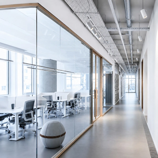
full height glass partition door opening integrated into the continuous wall line

Start Your Full-Height Partition Review

A preliminary review can begin with basic project information. Additional drawings and project requirements can be provided as the configuration is developed.

Minimum Information to Begin

A floor plan, simple layout, hand sketch, or basic wall dimensions.

Proposed wall height.

Helpful If Available

Preferred glass configuration

Door opening or door type

Ceiling, floor, and adjacent wall conditions

Project location or local requirements

Still Selecting the Wall Configuration?

Start with a configuration review to compare suitable SG systems, glass configurations, and connections to the ceiling, floor, and adjacent walls.

Have Drawings or Need Connection Details?

Request drawing support or CAD assistance to review the wall elevation, door opening, and key building connections.

Need Supporting Evidence?

Request a relevant report, certificate, or component document for the proposed configuration and specific project requirements.

Ready to Request a Quotation?

Request a quotation once the main wall dimensions, preferred configuration, door requirements, and project conditions are sufficiently defined.

A complete BOQ, final elevation, shop drawings, or full set of connection details is not required to begin. The ceiling type can be confirmed later, but it must be defined before the ceiling and other building connections are finalized.